Diferència entre revisions de la pàgina «Moteino LoRa»
| (Hi ha 2 revisions intermèdies del mateix usuari que no es mostren) | |||
| Línia 1: | Línia 1: | ||
'''Introducció''' | '''Introducció''' | ||
| − | Moteino és una placa de format petit que fa servir el | + | Moteino és una placa de format petit que fa servir el mateix microcontrollador que el popular Arduino però que està orientada a aplicacions de baix consum. Està dissenyada i comercialitzada per [https://lowpowerlab.com/shop/product/99 LowPowerLab] i es pot aconseguir des de la seva botiga per uns 25 dolars més enviament. |
| + | |||
| + | [[Fitxer:moteino_rfm95.jpg|600px|center]] | ||
| − | |||
La placa fa servir el mòdul RFM95 de HopeRF igual que moltes altres. Compte que tant el RFM95 com el RFM96 (per 433MHz) estan etiquetats iguals: RF96. Fixeu-vos en la imatge següent i la disposició dels components per identificar un o l'altre. Per TTN EU ens interessa el RFM95 a 868MHz. | La placa fa servir el mòdul RFM95 de HopeRF igual que moltes altres. Compte que tant el RFM95 com el RFM96 (per 433MHz) estan etiquetats iguals: RF96. Fixeu-vos en la imatge següent i la disposició dels components per identificar un o l'altre. Per TTN EU ens interessa el RFM95 a 868MHz. | ||
| − | [[Fitxer:rfm95_vs_rfm96.jpg]] | + | [[Fitxer:rfm95_vs_rfm96.jpg|600px|center]] |
| + | |||
'''Requeriments''' | '''Requeriments''' | ||
| Línia 15: | Línia 17: | ||
A més caldrà fer unes modificacions en el hardware per poder fer servir la llibreria. Bàsicament necessitem poder accedir al GPIO de RESET i a DIO1 i DIO2 que connectarem a D4, D5 i D6 respectivament. | A més caldrà fer unes modificacions en el hardware per poder fer servir la llibreria. Bàsicament necessitem poder accedir al GPIO de RESET i a DIO1 i DIO2 que connectarem a D4, D5 i D6 respectivament. | ||
| − | [[Fitxer:rfm95_pinout.png]] | + | [[Fitxer:rfm95_pinout.png|600px|center]] |
| + | |||
Aquí una imatge de com queda el mòdul amb les tres connexions fetes. | Aquí una imatge de com queda el mòdul amb les tres connexions fetes. | ||
| − | [[Fitxer:Moteino wires.jpg]] | + | [[Fitxer:Moteino wires.jpg|600px|center]] |
| + | |||
'''Exemple''' | '''Exemple''' | ||
| Línia 33: | Línia 37: | ||
Based on LMIC library example | Based on LMIC library example | ||
| − | This sketch | + | This sketch sends an incrementing number every minute |
// ----------------------------------------------------------------------------- | // ----------------------------------------------------------------------------- | ||
Revisió de 11:10, 31 gen 2018
Introducció
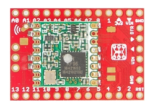
Moteino és una placa de format petit que fa servir el mateix microcontrollador que el popular Arduino però que està orientada a aplicacions de baix consum. Està dissenyada i comercialitzada per LowPowerLab i es pot aconseguir des de la seva botiga per uns 25 dolars més enviament.
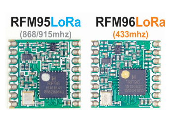
La placa fa servir el mòdul RFM95 de HopeRF igual que moltes altres. Compte que tant el RFM95 com el RFM96 (per 433MHz) estan etiquetats iguals: RF96. Fixeu-vos en la imatge següent i la disposició dels components per identificar un o l'altre. Per TTN EU ens interessa el RFM95 a 868MHz.
Requeriments
Aquest dispositiu està pensat per comunicació p2p sobre LoRa. Per fer servir TTN necessitem suport LoRaWan i per això farem servir la llibreria Arduino-LMIC de Matthijs Kooijman.
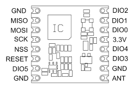
A més caldrà fer unes modificacions en el hardware per poder fer servir la llibreria. Bàsicament necessitem poder accedir al GPIO de RESET i a DIO1 i DIO2 que connectarem a D4, D5 i D6 respectivament.
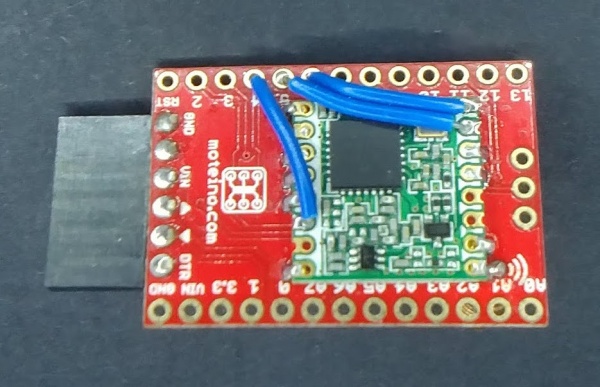
Aquí una imatge de com queda el mòdul amb les tres connexions fetes.
Exemple
/*

MOTEINO TTN EU NODE - ABP mode

Copyright (C) 2016-2018
Xose Pérez <xose dot perez at gmail dot com>
for The Things Network Catalunya Wiki (http://thethingsnetwork.cat)
Based on LMIC library example

This sketch sends an incrementing number every minute

// -----------------------------------------------------------------------------

Requirements:

* This sketch requires LMIC library by Matthijs Kooijman
  https://github.com/matthijskooijman/arduino-lmic

* Tested on Moteino LoRa (https://lowpowerlab.com/shop/product/99)
  but you will have to wire the folowing extra pins from the
  RFM95 module to Moteino ports:

  RFM95     Moteino
  --------  --------
  RESET     D4
  DIO1      D5
  DIO2      D6

RFM95 module pinout (top view, with the chip facing you in the top-left corner
of the module) and the corresponding Moteino PIN connected
(wire the ones marked with an asterisk *)

        |-------------|
    GND | GND    DIO2 | D6*
    D12 | MISO   DIO1 | D5*
    D11 | MOSI   DIO0 | D2
    D13 | SCK     3V3 | 3V3
    D10 | NSS    DIO4 |
    *D4 | RESET  DIO3 |
        | DIO5    GND | GND
    GND | GND     ANT |
        |-------------|

// -----------------------------------------------------------------------------

This program is free software: you can redistribute it and/or modify
it under the terms of the GNU General Public License as published by
the Free Software Foundation, either version 3 of the License, or
(at your option) any later version.

This program is distributed in the hope that it will be useful,
but WITHOUT ANY WARRANTY; without even the implied warranty of
MERCHANTABILITY or FITNESS FOR A PARTICULAR PURPOSE.  See the
GNU General Public License for more details.

You should have received a copy of the GNU General Public License
along with this program.  If not, see <http://www.gnu.org/licenses/>.

*/

#include <Arduino.h>
#include <lmic.h>
#include <hal/hal.h>
#include <SPI.h>

#ifndef CFG_eu868
    #error "This script is meant to connect to TTN EU network at 868MHz"
#endif

// -----------------------------------------------------------------------------
// Configuration
// -----------------------------------------------------------------------------

#define SERIAL_BAUD         115200
#define TX_INTERVAL         60

// ABP - Change to match your application configuration
static const u1_t PROGMEM NWKSKEY[16] = { 0x00, 0x00, 0x00, 0x00, 0x00, 0x00, 0x00, 0x00, 0x00, 0x00, 0x00, 0x00, 0x00, 0x00, 0x00, 0x00 };
static const u1_t PROGMEM APPSKEY[16] = { 0x00, 0x00, 0x00, 0x00, 0x00, 0x00, 0x00, 0x00, 0x00, 0x00, 0x00, 0x00, 0x00, 0x00, 0x00, 0x00 };
static const u4_t DEVADDR = 0x00000000;

// Pin mapping (see hardware changes above)
const lmic_pinmap lmic_pins = {
    .nss = 10,                  // NSS pin
    .rxtx = LMIC_UNUSED_PIN,
    .rst = 4,                   // RESET pin
    .dio = {2, 5, 6},           // DIO0, DIO1 and DIO2
};

// -----------------------------------------------------------------------------
// Globals
// -----------------------------------------------------------------------------

// These callbacks are only used in over-the-air activation, so they are
// left empty here (we cannot leave them out completely unless
// DISABLE_JOIN is set in config.h, otherwise the linker will complain).
void os_getArtEui (u1_t* buf) { }
void os_getDevEui (u1_t* buf) { }
void os_getDevKey (u1_t* buf) { }

// Job
static osjob_t sendjob;

// Value
unsigned long autoincrement = 0;

// -----------------------------------------------------------------------------
// LMIC
// -----------------------------------------------------------------------------

void ttnSend(osjob_t* j){

    // Check if there is not a current TX/RX job running
    if (LMIC.opmode & OP_TXRXPEND) {
        Serial.println(F("[TTN] Pending message"));
        return;
    }

    // Prepare buffer
    unsigned char data[4];
    data[0] = (autoincrement >> 24) & 0xFF;
    data[1] = (autoincrement >> 16) & 0xFF;
    data[2] = (autoincrement >>  8) & 0xFF;
    data[3] = (autoincrement >>  0) & 0xFF;

    // Prepare upstream data transmission at the next possible time.
    // Parameters are port, data, length, confirmed
    LMIC_setTxData2(1, data, 4, 0);

    Serial.println(F("[TTN] Packet queued"));

    // Next TX is scheduled after TX_COMPLETE event.
    autoincrement++;

}

// LMIC library will call this method when an event is fired
void onEvent(ev_t ev) {

    if (ev == EV_TXCOMPLETE) {

        Serial.println(F("[TTN] Packet sent"));

        if (LMIC.txrxFlags & TXRX_ACK) {
            Serial.println(F("[TTN] ACK Received"));
        }

        if (LMIC.dataLen) {
            Serial.print(F("[TTN] Received "));
            Serial.print(LMIC.dataLen);
            Serial.println(F(" bytes of payload"));
        }

        // Schedule next transmission
        os_setTimedCallback(&sendjob, os_getTime() + sec2osticks(TX_INTERVAL), ttnSend);

    }

}

void ttnSetup() {

    // LMIC init
    os_init();

    // Reset the MAC state. Session and pending data transfers will be discarded.
    LMIC_reset();

    // Set static session parameters. Instead of dynamically establishing a session
    // by joining the network, precomputed session parameters are be provided.
    // On AVR, these values are stored in flash and only copied to RAM
    // once. Copy them to a temporary buffer here, LMIC_setSession will
    // copy them into a buffer of its own again.
    uint8_t appskey[sizeof(APPSKEY)];
    uint8_t nwkskey[sizeof(NWKSKEY)];
    memcpy_P(appskey, APPSKEY, sizeof(APPSKEY));
    memcpy_P(nwkskey, NWKSKEY, sizeof(NWKSKEY));
    LMIC_setSession (0x1, DEVADDR, nwkskey, appskey);

    // Set up the channels used by the Things Network, which corresponds
    // to the defaults of most gateways. Without this, only three base
    // channels from the LoRaWAN specification are used, which certainly
    // works, so it is good for debugging, but can overload those
    // frequencies, so be sure to configure the full frequency range of
    // your network here (unless your network autoconfigures them).
    // Setting up channels should happen after LMIC_setSession, as that
    // configures the minimal channel set.
    LMIC_setupChannel(0, 868100000, DR_RANGE_MAP(DR_SF12, DR_SF7),  BAND_CENTI);      // g-band
    LMIC_setupChannel(1, 868300000, DR_RANGE_MAP(DR_SF12, DR_SF7B), BAND_CENTI);      // g-band
    LMIC_setupChannel(2, 868500000, DR_RANGE_MAP(DR_SF12, DR_SF7),  BAND_CENTI);      // g-band
    LMIC_setupChannel(3, 867100000, DR_RANGE_MAP(DR_SF12, DR_SF7),  BAND_CENTI);      // g-band
    LMIC_setupChannel(4, 867300000, DR_RANGE_MAP(DR_SF12, DR_SF7),  BAND_CENTI);      // g-band
    LMIC_setupChannel(5, 867500000, DR_RANGE_MAP(DR_SF12, DR_SF7),  BAND_CENTI);      // g-band
    LMIC_setupChannel(6, 867700000, DR_RANGE_MAP(DR_SF12, DR_SF7),  BAND_CENTI);      // g-band
    LMIC_setupChannel(7, 867900000, DR_RANGE_MAP(DR_SF12, DR_SF7),  BAND_CENTI);      // g-band
    LMIC_setupChannel(8, 868800000, DR_RANGE_MAP(DR_FSK,  DR_FSK),  BAND_MILLI);      // g2-band

    // TTN defines an additional channel at 869.525Mhz using SF9 for class B
    // devices' ping slots. LMIC does not have an easy way to define set this
    // frequency and support for class B is spotty and untested, so this
    // frequency is not configured here.

    // Disable link check validation
    LMIC_setLinkCheckMode(0);

    // TTN uses SF9 for its RX2 window.
    LMIC.dn2Dr = DR_SF9;

    // Set data rate and transmit power for uplink (note: txpow seems to be ignored by the library)
    LMIC_setDrTxpow(DR_SF7, 14);

    // Start job
    ttnSend(&sendjob);

}

// -----------------------------------------------------------------------------
// Main methods
// -----------------------------------------------------------------------------

void setup() {

    // Init serial port for debugging
    Serial.begin(115200);
    Serial.println("[MAIN] Startup");

    // Init LMIC library to work with TTN EU
    ttnSetup();

}

void loop() {

    // Keeps track of the scheduled jobs
    os_runloop_once();

}


